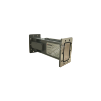
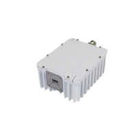
Here is the product information presented in English tables as requested.
📡 Product Overview
Aspect | Details |
|---|
Model | L-band Low-Noise Block Downconverter (1.2–1.3 GHz) |
Manufacturer | Shenzhen Huashi Digital Technology Co., Ltd. |
Application | L-band satellite/ground station front-ends, test and measurement, remote weak-signal reception, spectrum monitoring, and link gain shaping. |
Core Function | Integrates a low-noise amplifier (LNA) and downconverter to convert 1.2–1.3 GHz RF signals to a 20–120 MHz IF. |
Key Specs | • Conversion Gain: ≥ 45 dB (adjustable in 1 dB steps over a 30 dB range)
• Remote Control: RS232 / RS422 / RS485
• RF Connector: SMA-K (50 Ω) |
Design | Compact and easy to integrate. |
📊 Key Specifications
Item | Parameter |
|---|
Input frequency | 1.2–1.3 GHz (1200–1300 MHz) |
Output IF | 20–120 MHz |
Conversion gain | ≥ 45 dB |
Gain adjustability | 30 dB range, 1 dB step |
Gain stability | 0.2 dB / 10 minutes |
Noise figure | 2 dB (typical) |
Input power range | –38 ~ –68 dBm |
Output P1dB | ≥ +17 dBm |
Control interface | RS232 / RS422 / RS485 |
RF connectors | SMA-K (50 Ω) |
✨ Features
Feature | Description |
|---|
High gain with low noise | Maintains ≥ 45 dB conversion gain while keeping the noise figure as low as 2 dB, increasing weak-signal link margin. |
Fine gain control | 1 dB step, 30 dB range for system-level gain shaping and dynamic range optimization. |
Industrial-grade stability | 0.2 dB / 10 minutes gain stability for long-term, continuous operation and stability-sensitive applications. |
Wide input tolerance | Accepts –38 ~ –68 dBm input range, compatible with various front-end attenuator/amplifier configurations. |
Strong drive capability | Output P1dB ≥ +17 dBm to drive subsequent stages or long cable runs. |
Multi-interface remote management | RS232 / RS422 / RS485 options for easy integration with network management, monitoring, and automated test systems. |
⚙️ Applications & Setup
Category | Details |
|---|
Typical Applications | • L-band satellite/ground station front ends
• Remote weak-signal reception
• Spectrum monitoring and analysis
• Link budget optimization
• AGC/ALC preamplifier stages |
Interface & Power | • RF Ports: SMA-K (50 Ω)
• Control: RS232/RS422/RS485 via shielded twisted pair (STP) with proper grounding.
• Power: Refer to the equipment nameplate/communication protocol. A host controller or PC is required for remote adjustment and status readback. |
Setup & Debugging | Gain setting: Adjust IF gain so the overall link operates in the linear region, then fine-tune in 1 dB steps to balance C/N and distortion.
Input level: Keep the front-end signal within –38 ~ –68 dBm to avoid distortion; add/remove attenuation as needed.
Cabling: Use low-loss 50 Ω coaxial cables and keep them as short as possible; ensure connectors are tightened and weatherproofed.
Control: Use RS232/RS422/RS485 to read status and alarms; configure communication parameters (address, baud rate, parity) per the manual. |